- 您现在的位置:买卖IC网 > Sheet目录335 > ISL97671AIRZ (Intersil)IC LED DVR PWM CTRL 6CH 20QFN
�� �
�
�ISL97671A�
�and� the� PWM� duty� cycle� in� percent,� as� shown� in� Equation� 5:�
�cycle� is� 60%� dimming� at� 1kHz,� the� resultant� PWM� duty� cycle� is�
�I� LED� (� ave� )� =� I� LED� � PWM�
�(EQ.� 5)�
�48%� dimming� at� 200Hz.�
�I� LED� (� ave� )� =� I� LED� � (� BRT� ?� 255� )�
�Method� 1� (SMBus/I� 2� C� Controlled� Dimming)�
�The� average� LED� channel� current� is� controlled� by� the� internally�
�generated� PWM� signal,� as� shown� in� Equation� 6:�
�(EQ.� 6)�
�where� BRT� is� the� PWM� brightness� level� programmed� in� the�
�Register� 0x00.� BRT� ranges� from� 0� to� 255� in� decimal� and� defaults�
�to� 255� (0xFF).� BRT� =� 0� disconnects� all� channels.�
�To� use� only� the� SMBus/I� 2� C� controlled� PWM� brightness� control,�
�users� need� to� set� Register� 0x01� to� 0x05.� Alternatively,� the� same�
�operation� can� be� obtained� by� leaving� Register� 0x01� at� its� default�
�value� of� 0x01� (DPST� mode)� and� connecting� the� PWM� input� to�
�VDC,� so� that� the� dimming� level� depends� only� on� the� BRT� register.�
�In� DPST� mode,� the� ISL97671A� features� 8-bit� dimming� resolution;�
�it� calculates� the� dimming� level� by� taking� the� 8� most� significant�
�bits� of� the� product� of� the� PWMI� duty� cycle� (digitized� with� 8-bit�
�resolution)� and� of� the� BRT� I� 2� C� register.�
�Method� 4� (Direct� PWM� Mode)�
�Direct� PWM� Dimming� mode� is� selected� when� F� PWM� is� tied� to� V� DC�
�and� SMBCLK/SMBDAT� are� grounded.� The� current� of� the� 6�
�channels� will� follow� the� incoming� PWM� signal’s� frequency� and�
�duty� cycle.� The� minimum� duty� cycle� can� be� as� low� as� 0.007%� at�
�200Hz� (or� equivalent� pulse� width� of� 350ns).� This� ultra� low� duty�
�cycle� dimming� performance� can� be� achieved� if� no� channel�
�capacitor� is� present.� Also� in� Direct� PWM� Dimming� mode� the�
�Phase� Shift� function� will� be� disabled.�
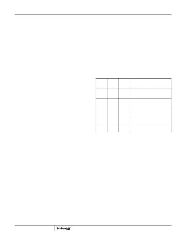
�TABLE� 1.� DIMMING� MODE� SELECTION�
�The� PWM� dimming� frequency� is� adjusted� by� a� resistor� at� the�
�SMBCLK/�
�SMBDAT/�
�FPWM� pin.�
�Method� 2� (PWM� Controlled� Dimming� with� Settable� Dimming�
�Frequency)�
�The� average� LED� channel� current� can� also� be� controlled� by� the� duty�
�SCL� PIN� SDA� PIN�
�SIGNAL� SIGNAL� FPWM� PIN�
�SMBUS� /I� 2� C� SMBUS/I� 2� C� Resistor� to�
�clock� data� ground�
�DIMMING� METHOD�
�0x01� REGISTER� SELECTION�
�Set� to� 0x05,� or� set� to� Method� 1� (SMBUS/I� 2� C�
�0x01� and� connect� PWM� controlled� dimming)�
�to� VDC�
�cycle� of� external� PWM� signal,� as� shown� in� Equation� 7:�
�I� LILED� (� ave� )� =� I� LED� � PWMI�
�(EQ.� 7)�
�SMBUS� /I� 2� C� SMBUS/I� 2� C� Resistor� to�
�clock� data� ground�
�Set� to� 0x03,� or� set� to�
�0x01� and� not� program�
�register� 0x00�
�Method� 2� (PWM� controlled�
�with� settable� dimming�
�frequency)�
�The� PWM� dimming� frequency� is� adjusted� by� a� resistor� at� the�
�FPWM� pin.� The� PWM� input� cannot� be� low� for� more� than� 30.5ms�
�Grounded�
�Grounded�
�Resistor� to�
�ground�
�N/A�
�Method� 2� (PWM� controlled�
�with� settable� dimming�
�frequency)�
�or� else� the� driver� will� enter� shutdown.�
�SMBUS� /I� 2� C� SMBUS/I� 2� C� Resistor� to�
�Set� to� 0x01�
�Method� 3� (DPST� mode)�
�To� use� externally� applied� PWM� signal� only� for� brightness� control,�
�clock�
�data�
�ground�
�users� need� to� set� Register� 0x01� to� 0x03.� Alternatively,� the� same�
�operation� can� be� obtained� by� leaving� Register� 0x01� at� its� default�
�Grounded�
�Grounded�
�Tie� to� VDC�
�N/A�
�Method� 4� (Direct� PWM�
�dimming)�
�value� of� 0x01� (DPST� mode),� and� not� program� Register� BRT,� so�
�that� it� contains� its� default� value� of� 0xFF.� A� third� way� to� obtain� this�
�mode� of� operation� is� to� tie� both� SCL� and� SDA� to� ground.�
�Method� 3� (DPST� Mode)�
�PWM� Dimming� Frequency� Adjustment�
�For� dimming� methods� 1-3,� the� PWM� dimming� frequency� is� set� by�
�an� external� resistor� at� the� FPWM� pin� as:�
�6.66� � 10�
�F� PWM� =� ------------------------�
�The� average� LED� channel� current� can� also� be� controlled� by� the�
�product� of� the� SMBus/I� 2� C� controlled� PWM� and� the� external� PWM�
�7�
�RFPWM�
�(EQ.� 11)�
�signals� as:�
�I� LED� (� ave� )� =� I� LED� xPWM� DPST�
�Where:�
�PPWM� DPST� =� BRT� ?� 255� � PWMI�
�Therefore:�
�I� LED� (� ave� )� =� I� LED� � BRT� ?� 255� � PWMI�
�(EQ.� 8)�
�(EQ.� 9)�
�(EQ.� 10)�
�where� F� PWM� is� the� PWM� dimming� frequency� and� R� FPWM� is� the�
�setting� resistor.�
�The� maximum� PWM� dimming� frequency� is� 30kHz� when� the� duty�
�cycle� is� from� 0.4%� to� 100%.�
�Phase� Shift� Control�
�For� dimming� methods� 1-3,� the� ISL97671A� is� capable� of� delaying�
�the� phase� of� each� current� source� to� minimize� load� transients.� By�
�Where� BRT� is� the� value� held� in� Register� 0x00� (default� setting�
�0xFF)� controlled� by� SMBus/I� 2� C� and� PWMI� is� the� duty� cycle� of� the�
�incoming� PWM� signal.� In� this� way,� the� users� can� change� the�
�PWM� current� in� ratiometric� manner� to� achieve� DPST� compliant�
�backlight� dimming.� To� use� the� DPST� mode,� users� need� to� set�
�Register� 0x01� to� 0x01.� The� PWM� dimming� frequency� is� adjusted�
�by� a� resistor� at� the� FPWM� pin.�
�For� example,� if� the� SMBus/I� 2� C� controlled� PWM� duty� is� 80%�
�dimming� at� 200Hz� (see� Equation� 11)� and� the� external� PWM� duty�
�12�
�default,� phase� shifting� is� disabled� as� shown� in� Figure� 20� where�
�the� channels� PWM� currents� are� switching� at� the� same� time.�
�FN7709.3�
�November� 30,� 2012�
�发布紧急采购,3分钟左右您将得到回复。
相关PDF资料
ISL97672AIRZ
IC LED DRVR LOW DIMMING 20QFN
ISL97672BIRZ
IC LED DRVR BACKLIGHT 20QFN
ISL97675IRZ-TK
IC LED DVR PWM CTRL 4CH 20QFN
ISL97677IRZ
IC LED DVR PWM CTRL 8CH 32QFN
ISL97678IRZ
IC LED DVR PWM DIMMING 8CH 32QFN
ISL97686IRTZ
IC LED DRVR BACKLIGHT 28TQFN
ISL97691IRTZ-TK
IC LED DRVR BACKLIGHT 3D 16TQFN
ISL97693IRTZ-TK
IC LED DRVR BACKLIGHT 16TQFN
相关代理商/技术参数
ISL97671AIRZ-T
功能描述:IC LED DRVR 6-CH BACKLIGHT 20QFN RoHS:是 类别:集成电路 (IC) >> PMIC - LED 驱动器 系列:- 标准包装:60 系列:- 恒定电流:- 恒定电压:- 拓扑:线性(LDO),PWM,升压(升压) 输出数:8 内部驱动器:是 类型 - 主要:背光 类型 - 次要:RGB,白色 LED 频率:500kHz ~ 1.5MHz 电源电压:4.75 V ~ 26 V 输出电压:45V 安装类型:* 封装/外壳:* 供应商设备封装:* 包装:* 工作温度:-40°C ~ 85°C
ISL97671AIRZ-TK
功能描述:IC LED DVR PWM CTRL 6CH 20QFN RoHS:是 类别:集成电路 (IC) >> PMIC - LED 驱动器 系列:- 标准包装:60 系列:- 恒定电流:- 恒定电压:- 拓扑:线性(LDO),PWM,升压(升压) 输出数:8 内部驱动器:是 类型 - 主要:背光 类型 - 次要:RGB,白色 LED 频率:500kHz ~ 1.5MHz 电源电压:4.75 V ~ 26 V 输出电压:45V 安装类型:* 封装/外壳:* 供应商设备封装:* 包装:* 工作温度:-40°C ~ 85°C
ISL97671IRZ
制造商:Intersil Corporation 功能描述:6-CH LED DRIVER WITH I2C CONTROL - Rail/Tube
ISL97671IRZ-EVALZ
功能描述:BOARD EVALUATION FOR ISL97671 RoHS:是 类别:编程器,开发系统 >> 评估板 - LED 驱动器 系列:- 标准包装:1 系列:PowerWise® 电流 - 输出 / 通道:20mA 输出及类型:1,非隔离 输出电压:17V 特点:可调光 输入电压:2.7 ~ 5.5 V 已供物品:板 已用 IC / 零件:LM3508 相关产品:LM3508TLX-ND - IC LED DRVR WHT BCKLGT 9USMDLM3508TLDKR-ND - IC LED DRVR WHT BCKLGT 9MICROSMDLM3508TLCT-ND - IC LED DRVR WHT BCKLGT 9MICROSMDLM3508TLTR-ND - IC LED DRVR WHT BCKLGT 9MICROSMD
ISL97671IRZ-T
制造商:Intersil Corporation 功能描述:6-CH LED DRIVER WITH I2C CONTROL - Tape and Reel
ISL97671IRZ-TK
制造商:Intersil Corporation 功能描述:6-CH LED DRIVER WITH I2C CONTROL, 1K T&R - Tape and Reel
ISL97672AIRZ
功能描述:IC LED DRVR LOW DIMMING 20QFN RoHS:是 类别:集成电路 (IC) >> PMIC - LED 驱动器 系列:- 产品培训模块:Lead (SnPb) Finish for COTS
Obsolescence Mitigation Program 标准包装:2,500 系列:- 恒定电流:- 恒定电压:- 拓扑:升压(升压),切换式电容器(充电泵) 输出数:1 内部驱动器:是 类型 - 主要:背光 类型 - 次要:白色 LED 频率:625kHz ~ 875kHz 电源电压:2.7 V ~ 5.3 V 输出电压:5V 安装类型:表面贴装 封装/外壳:10-TFSOP,10-MSOP(0.118",3.00mm 宽) 供应商设备封装:10-µMAX 包装:带卷 (TR) 工作温度:-40°C ~ 85°C
ISL97672AIRZ-T
功能描述:IC LED DRVR LOW DIMMING 20QFN RoHS:是 类别:集成电路 (IC) >> PMIC - LED 驱动器 系列:- 产品培训模块:Lead (SnPb) Finish for COTS
Obsolescence Mitigation Program 标准包装:2,500 系列:- 恒定电流:- 恒定电压:- 拓扑:升压(升压),切换式电容器(充电泵) 输出数:1 内部驱动器:是 类型 - 主要:背光 类型 - 次要:白色 LED 频率:625kHz ~ 875kHz 电源电压:2.7 V ~ 5.3 V 输出电压:5V 安装类型:表面贴装 封装/外壳:10-TFSOP,10-MSOP(0.118",3.00mm 宽) 供应商设备封装:10-µMAX 包装:带卷 (TR) 工作温度:-40°C ~ 85°C